Calculator for selecting profile pipes for a canopy. Calculation of an arched metal truss for a canopy Calculation of a metal structure of a canopy
Metal trusses for a canopy are one of the most basic structures. They are often erected on summer cottages and territories country houses. This simple designs from a frame, covering and additional elements. You can use them to make a canopy that covers the space allocated for storing things, or to create a mini parking lot for a car. You can do the entire assembly yourself, but to make the truss strong and durable, correct calculations are necessary.
Sheds are designed to provide space for storing things or constructing a mini parking lot for a car.
Types of structures
Trusses are made from rectangular profiles or metal corners. The material is selected depending on the type of structure and type of belts. The belts are the basis of the farm; they are located below and above the structure and form its spatial outline. For the manufacture of small structures, profile pipes are used.
Farms have several forms:
- Polygonal. This type of trusses is designed for installation on spans of 10 meters or more in length. If you install a canopy in a small area, the structure is equipped with additional parts, which complicates its assembly. Canopies manufactured in production and having an arched shape are an exception.
- Triangular. This is a gable canopy with a slope of 22-30 degrees. It is often installed in regions where there is a large amount of snowfall. The disadvantage of the product is the sharp knot at the base of the structure and the long supports located in the center. These areas must be correctly calculated and marked on the drawing. Polycarbonate trusses for canopies of small sizes have proportions in relation to height and width of no more than ¼, 1/5.

There are many types of frame trusses, they differ in the complexity of construction and have a different number of advantages
- Parallel. According to the drawing, the slope of the finished product is no more than 1.5%. In this case, the ratio of height and length varies from 1/6 to 1/8. The product is used for a flat canopy, which is planned to be finished with roll cladding. The belt rods that create the spatial lattice have a uniform length, which results in a minimum of connecting nodes.
- Arched. This is the most convenient farm design. It allows you to hide bending lines in the cross sections of the frame. In addition, the arch material experiences constant compression. Therefore, all calculations are carried out according to a simplified template, since the weight from the roof, mounting sheathing and snow load will be equally distributed throughout the canopy.
- Trapezoidal. The tilt angle of the frame ranges from 6 to 150 degrees. Moreover, its height and length have proportions of 1/6. The product is characterized by a rigid frame.
- The entire load acts on the supports of the structure and is directed downward. Because of this, it is evenly distributed. Consequently, the support pillars have good resistance against compression. This allows you to withstand the additional weight from snow cover.
- Since the arches are less rigid, the load is distributed unevenly. Because of this, under the influence of load they unbend. As a result, a force appears that acts on the supports located at the top of the structure.
- The length of the frame must exactly match the length of the span (the interval overlapping the profile).
- Depending on the developed angle and characteristics of the outline, the height of the structure is determined. If the structure is triangular, then its height varies from 1/5 or ¼ of the length. The ratio of straight roofing is 1/8.
- The angle of inclination of the grille to the belt varies from 35 to 50 degrees. The average value is 45 degrees.
- The width of the panel will help you correctly calculate the gap between the nodes. They are always identical. If the frame has a long span (25-30 meters or more), then it requires a construction lift. It is calculated additionally. These calculations will help determine the load level and select the appropriate value profile pipes.
- So that the building has a beautiful appearance and at the same time withstand high loads, the distance between the arches is 105 cm. In this case, the height of the structure will be 150 cm.
- The sector length formula π × R × α ÷ 180 will help calculate the length of the profile along the lower chord. According to the drawing: R = 410 cm, α ÷ 160°. Substituting the numbers, it turns out: 3.14 × 410 × 160 ÷ 180 = 758 (cm).
- The frame nodes are placed on the lower belt. The distance between them must be at least 55 cm. An individual calculation is required to install the extreme units.
This video shows how to draw a truss drawing for a canopy:
What level of load the structure can withstand depends on the thickness of the profile pipe. The thicker it is, the stronger the structure. For large structures, it is better to choose a square profile with a cross-section of 30-50×30-50 mm. Pipes with a smaller cross-section are used for a small frame.
The metal profile is highly durable and compared to a solid metal bar it weighs much less. The material bends easily, this allows you to create arched and dome-shaped structures.
Ready-made metal profile canopy trusses have affordable price. To ensure that the material lasts a long time, it is painted or coated with a primer, which will protect it from corrosion.
Polycarbonate truss
To assemble a polycarbonate canopy truss, you need to draw up a detailed diagram. Each part indicated in the diagram must have exact dimensions. Details from complex design drawn in an additional drawing.
To select the type of structure and the number of component parts, it is necessary to make calculations. Additionally, they study the level of precipitation in their region. This data will help create a structure of the required strength. The most simplified type of truss is an arc (pipe) with a round or square cross-section. Despite the fact that this is the most cheap option Of all, polycarbonate pipes are not very reliable.
Load distribution:
Incorrect calculation of a truss for a canopy threatens that the bases of the pillars will become bent and deformed.
When calculating a polycarbonate truss, the height and length of the frame are taken into account, as well as the angle of inclination of the lattice and the distance between the modules. Calculation example:
For example, the calculation for a single-pitched frame measuring 4 × 6 m is as follows. The structure is created from a 3x3 cm profile. Its thickness is 0.12 cm. The length of the lower belt is 310 cm, and the upper one is 390 cm. Vertical supports are mounted between the belts. The height of the largest will be 60 cm, the other three will be shortened evenly. After installing the supports, there are places that need to be strengthened. They are equipped with slanting lintels (thin profile with a cross-section of 2×2 cm). In places where the belts are connected, racks are not installed.
If the canopy is long (6-7 meters), then 5 such structures are installed. They are placed at a distance of 1.5 m. Each module is secured with transverse jumpers. A profile with a cross section of 2×2 cm is used as jumpers.
It is placed at a distance of 50 cm from each other and secured to the upper belt. The polycarbonate sheathing is attached to the lintels.
Arch frame
Due to its special structure, an arched truss for a canopy also requires precise calculations. They are necessary to ensure that the acting load is distributed evenly over the entire surface. And this is only possible thanks to the correct and even shape of the frame.
Making an arched frame 6 meters long:
Video on how to use the calculator:
The profile of the pillars is selected depending on the width of the canopy (from the truss side, below in the sketch according to dimension “B”)
For canopy width:
up to 4000 mm column profile 60x60x2.5
over 4000 mm to 6000 mm column profile 80x80x3
over 6000 mm up to 8000 mm profile 100x100x3
over 8000 mm to 10000 mm profile 120x120x4
Determination of crossbar strength:
the calculator will show a positive number as a percentage of safety margin if the profile is selected correctly and a negative safety margin for a profile that cannot be used.
Determination of the “noodle” part for strength:

the rectangular “noodle” part is taken into account in the “flat” position and not “on the edge”
Definition of a complex truss for strength:
The weakest point of a truss is its middle, trusses break in the middle when the canopy cannot withstand the snow load, therefore, the calculator will show the breaking strength of the truss in the middle of the truss. weak spot
Dimension "A" for any truss you have in mind, triangular, square, etc., is taken at the midpoint of the overall length of the truss between the top and bottom pipes.

Definition of a simple truss for strength:

The canopy truss can be made of one link - a corrugated pipe or an I-beam. The loads on this link are enormous due to the fallen snow. Checking the snow load is mandatory here!
We will consider the I-beam only in the position “like a rail to the ground”, its dimensions according to GOST 26020-83 (I-beam No. 10 - its height is 100 mm, No. 14 - height 140, etc.), and we will consider the corrugated pipes as “flat” and “on edge"
The inclination angle is neglected, you can manually add a percentage of the inclination angle, or leave it as is, since it only affects the increase in strength.
Determining the strength of the system
transom + sub-transom truss
It often happens that the distance between the pillars needs to be increased, and the crossbar, no matter how powerful it is laid, does not pass the calculation of the snow load. This problem is solved by installing an additional sub-transom truss, and the pipes of the sub-transom truss can be made from a much smaller profile section. The problem arises - what profile parameter and what width of the crossbar truss should be in order to achieve sufficient strength without overpayments and without creating unnecessary clutter in the canopy. Of course, we are talking about a crossbar farm, filled with triangular shapes, as shown in the figure, and not in squares. The calculator will show the strength of the system by adding up the flexural resistance of the main transom plus the resistance of the sub-transom truss bottom tube up to the tensile yield point, rather than the flexural resistance of the sub-transom truss when it is incorrectly filled with square shapes, rendering the truss useless.

Note: this section already takes into account the safety factor (1.3), that is, for example, the calculator showed a safety factor of 0%, which means the truss is designed normally, with a safety factor (1.3)..
Without using any formulas, engineering calculations, programs, tables!
We do not fool the reader with phrases - “here we need to take into account...”, “calculate...”, “select from engineering tables...”, as is done on all sites! All formulas, accounting, selections, snips, state standards, assortments are hidden inside the calculator.
Here is your canopy - here are your planned dimensions! Enter your desired dimensions and the calculator will show you the safety factor of the selected professional pipes as a percentage. If the safety factor is positive, the canopy part will be considered calculated by the laws of strength of materials using all SNPs, GOSTs, assortments, and ifWhen ordering a product at our production site, we will confirm the results of this calculator with additional with a link to GOST assortments of professional pipes.
Our calculator is aimed at clients of gardening associations, cottage communities, and other private owners who need a quick, informed selection of corrugated pipes for sheds on outbuildings, car sheds, and extensions to buildings. Since often, in the absence of such a calculator, lack of experience, clients of "Garden and Vegetable Garden" undertake construction without any justification at all, either underestimating the strength, or, on the contrary, spending extra money, overestimating the strength. Therefore, the purpose of the calculator is only to guide the client in the right direction. For the construction of industrial buildings and workshops, industrial hangars and other large structures, a more detailed calculation is required. For example, in an industrial structure, each link of a truss must be calculated (in addition to taking into account the yield strength of tensile and bending in this calculator) for flexibility in compression and torsion, the parameter of which is taken into account before this link is used in the manufacture of the truss, before rolling on a pipe bender and filling with triangular elements and other parameters with their calculations. But in any case, if you want to build “something” relying only on “experience” and not on calculations, then it is better to use this calculator. Also, on this calculator you can set the safety margin yourself, for example 50%, 80%, choosing the strength yourself relative to your budget. For example, the trusses of our production workshop have a reserve of 80%, and can withstand not only snow, but also a crane beam that carries heavy loads. In any case, of course, you need to adhere to basic rules during construction, for example, you cannot use loads across the links, only along them. For example, in a truss, the place where it rests on the crossbar should not be empty, that is, without filling (that is, above the crossbar in the truss, there must be a link to fill the truss! Very often trusses break for this reason!). To install the “noodle” part, it is better to provide vertical filling links or the intersection of triangular fillings under it in the truss. It is better to make truss fillings from a thinner profile and more often than from a powerful one and rarely, since you should not forget that the load on the triangular filling links is along the axis and is insignificant, and the horizontal pipes of the trusses have a bending load component, and the loads on horizontal pipes huge, compared to the insignificant loads of the truss filling pipes.
-
Sheds are classified as the simplest structures that are erected on a suburban or summer cottage. They are used for a variety of purposes: as a parking lot, storage area and many other options.
Structurally, the canopy is extremely simple. This
- frame, the main element of which is trusses for canopies, which are responsible for the stability and strength of the structure;
- coating. It is made of slate, polycarbonate, glass or corrugated sheet;
- additional elements. As a rule, these are decoration elements that are located inside the structure.
The design is quite simple, and it also weighs little, so you can assemble it with your own hands right on the site.
However, in order to get a practical, correct canopy, you first need to ensure its strength and long-term operation. To do this, you should know how to calculate a truss for a canopy, make it yourself and weld it or buy ready-made ones.
Metal trusses for canopies

This design consists of two belts. The upper and lower chords are connected through braces and vertical posts. It is able to withstand significant loads. One such product, weighing from 50–100 kg, can replace metal beams three times larger in weight. With proper calculation, the metal truss in, channels or does not deform or bend when exposed to loads.
A metal frame experiences several loads at the same time, which is why it is so important to know how to calculate a metal truss in order to accurately find the equilibrium points. This is the only way the structure can withstand even very high impacts.
How to choose material and cook them correctly

Creation and self installation canopies are possible with small dimensions of the structure. Trusses for canopies, depending on the configuration of the belts, can be made of profiles or steel angles. For relatively small structures, it is recommended to choose profile pipes.
Such a solution has a number of advantages:
- The load-bearing capacity of a profile pipe is directly related to its thickness. Most often, to assemble the frame, a material with a square cross-section of 30-50x30-50 mm is used, and for small structures, pipes of a smaller cross-section are suitable.
- For metal pipes They are characterized by greater strength and yet they weigh much less than a solid metal bar.
- Pipes are bent - a quality necessary when creating curved structures, for example, arched or domed.
- The price of trusses for sheds is relatively small, so buying them will not be difficult.
On a note
The metal frame will last much longer if it is protected from corrosion: treated with a primer and painted.
- On such a metal frame you can conveniently and quite simply lay almost any sheathing and roofing.
Methods for connecting profiles
How to weld a canopy
Among the main advantages of profile pipes, the non-shaped connection should be noted. Thanks to this technology, a truss for spans not exceeding 30 meters is structurally simple and relatively inexpensive. If its upper belt is sufficiently rigid, then the roofing material can be supported directly on it.
The formless welded joint has a number of advantages:
- The weight of the product is significantly reduced. For comparison, we note that riveted structures weigh 20%, and bolted structures weigh 25% more.
- Reduces labor and manufacturing costs.
- welding cost is low. Moreover, the process can be automated if you use devices that allow uninterrupted feeding of welded wire.
- the resulting seam and the attached parts are equally strong.
One of the disadvantages is the need to have experience in welding.
Bolt-on mounting
Bolted connections of profile pipes are not used very rarely. It is mainly used for collapsible structures.
The main advantages of this type of connection include:
- Simple assembly;
- No need for additional equipment;
- Possible dismantling.
But at the same time:
- The weight of the product increases.
- Additional fasteners will be required.
- Bolted connections are less strong and reliable than welded ones.

How to calculate a metal truss for a canopy made from a profile pipe

The structures being erected must be sufficiently rigid and strong to withstand various loads, therefore, before their installation, it is necessary to calculate the truss from the profile pipe for the canopy and draw up a drawing.
When calculating, as a rule, they resort to the help of specialized programs taking into account the requirements of SNiP (“Loads, impacts”, “Steel structures”). You can calculate a metal truss online using the metal profile canopy calculator. If you have the appropriate engineering knowledge, you can carry out the calculation yourself.
On a note
If the main design parameters are known, you can look for a suitable finished project, among those posted on the Internet.

Design work is carried out on the basis of the following initial ones:
- Drawing. The configuration of the frame belts depends on the type of roof: single or gable, hip or arched. The most simple solution can be considered a single-pitched truss made from a profile pipe.
- Design dimensions. The larger the trusses are installed, the greater the load they can withstand. The angle of inclination is also important: the greater it is, the easier it will be to remove snow from the roof. For the calculation, you will need data on the extreme points of the slope and their distance from each other.
- Dimensions of roofing material elements. They play a crucial role in determining the pitch of the trusses for a canopy, say. By the way, this is the most popular coating for structures built on their own plots. They bend easily, so they are suitable for constructing curved coverings, for example, arched ones. All that matters is how to do it right calculate a polycarbonate canopy.
The calculation of a metal truss from a profile pipe for a canopy is performed in a certain sequence:
- determine the span corresponding to the technical specifications;
- to calculate the height of the structure, substitute the span dimensions according to the presented drawing;
- set the slope. According to the optimal shape of the roof of the structure, the contours of the belts are determined.
On a note
The maximum possible pitch of trusses for a canopy when using a profile pipe is 175 cm.
How to make a polycarbonate truss

The first stage of making your own trusses from a profile pipe for a canopy is to draw up a detailed plan, which should indicate the exact dimensions of each element. In addition, it is advisable to prepare an additional drawing of structurally complex parts.
As you can see, before you make trusses yourself, you need to be well prepared. Let us note once again that while the choice of product shape is guided by aesthetic considerations, a calculation path is required to determine the structural type and number of constituent elements. When checking the strength of a metal structure, it is also necessary to take into account data on atmospheric loads in a given region.
The arc is considered an extremely simplified variation of the truss. This is one profiled pipe with a round or square cross-section.
Obviously, this is not only the simplest solution, it is also cheaper. However, polycarbonate canopy poles have certain disadvantages. In particular, this concerns their reliability.

arched canopies photos
Let's analyze how the load is distributed in each of these options. The design of the truss ensures uniform distribution of the load, that is, the force acting on the supports will be directed, one might say, strictly downward. This means that the support pillars perfectly resist compression forces, that is, they can withstand the additional pressure of the snow cover.
The arches do not have such rigidity and are not able to distribute the load. To compensate for this kind of impact, they begin to unbend. The result is a force placed on the supports at the top. If we take into account that it is applied to the center and directed horizontally, then the slightest error in calculating the base of the pillars will, at the very least, cause their irreversible deformation.
An example of calculating a metal truss from a profile pipe
The calculation of such a product assumes:
- determination of the exact height (H) and length (L) of the metal structure. The latter value must exactly correspond to the span length, that is, the distance overlapping the structure. As for the height, it depends on the designed angle and contour features.
In triangular metal structures, the height is 1/5 or ¼ of the length, for other types with straight belts, for example, parallel or polygonal - 1/8.
- The angle of the grid braces ranges from 35–50°. On average it is 45°.
- It is important to determine the optimal distance from one node to another. Usually the required gap coincides with the width of the panel. For structures with a span length of more than 30 m, it is necessary to additionally calculate the construction lift. In the process of solving the problem, you can obtain the exact load on the metal structure and select the correct parameters for the profile pipes.

As an example, consider the calculation of trusses for a standard 4x6 m lean-to structure.
The design uses a 3 by 3 cm profile, the walls of which are 1.2 mm thick.
The lower belt of the product has a length of 3.1 m, and the upper one – 3.90 m. Between them, vertical posts made of the same profile pipe are installed. The largest of them has a height of 0.60 m. The rest are cut out in descending order. You can limit yourself to three racks, placing them from the beginning of the high slope.

The areas that are formed in this case are strengthened by installing diagonal lintels. The latter are made of a thinner profile. For example, a pipe with a cross section of 20 by 20 mm is suitable for these purposes. At the point where the belts meet, stands are not needed. On one product you can limit yourself to seven braces.
Five similar structures are used per 6 m length of the canopy. They are laid in increments of 1.5 m, connected by additional transverse jumpers made from a profile with a section of 20 by 20 mm. They are fixed to the upper chord, arranged in increments of 0.5 m. The polycarbonate panels are attached directly to these jumpers.
Calculation of an arched truss

The manufacture of arched trusses also requires precise calculations. This is due to the fact that the load placed on them will be distributed evenly only if the created arc-shaped elements have ideal geometry, that is, the correct shape.
Let's take a closer look at how to create an arched frame for a canopy with a span of 6 m (L). We will take the distance between the arches to be 1.05 m. With a product height of 1.5 meters, the architectural structure will look aesthetically pleasing and will be able to withstand high loads.
When calculating the profile length (mн) in the lower belt, use the following formula for the sector length: π R α:180, where the parameter values for this example in accordance with the drawing are equal, respectively: R= 410 cm, α÷160°.

After substitution we have:
3.14 410 160:180 = 758 (cm).
The structural units should be located on the lower chord at a distance of 0.55 m (rounded) from each other. The position of the extremes is calculated individually.
In cases where the span length is less than 6 m, welding of complex metal structures is often replaced by a single or double beam, bending the metal profile to a given radius. Although there is no need to calculate the arched frame, the correct selection of a profiled pipe still remains relevant. After all, the strength of the finished structure depends on its cross-section.
Calculation of an arched truss from a profile pipe online
How to calculate the arc length for a polycarbonate canopy
 The arc length of an arch can be determined using Huygens' formula. The middle is marked on the arc, designated by point M, which is located on the perpendicular CM drawn to the chord AB, through its middle C. Then you need to measure the chords AB and AM.
The arc length is determined by the Huygens formula: p = 2l x 1/3 x (2l – L), where l is the chord AM, L is the chord AB)
The relative error of the formula is 0.5% if the arc AB contains 60 degrees, and as the angular measure decreases, the error drops significantly. For an arc of 45 degrees. it is only 0.02%.
To figure out how to calculate a polycarbonate canopy, you need to clearly imagine the structure and draw up a plan or drawing of the building. By and large, polycarbonate panels are just a covering that defines the total area, but in addition to this, there are also racks and a rafter system. In addition, among necessary materials There will be connecting, corner and end profiles, fastening material and (possibly) lighting. It is important to calculate every detail in order to obtain a strong and durable structure.
What parameters to consider when calculating polycarbonate for a canopy?
Bent roof on garden plot
Please note that the strength of polycarbonate is much higher than the similar characteristics of glass (200 times), plastic and polyvinyl chloride. But not all panels can be bent, so their structure should be taken into account (sheets with triangular cells cannot be bent).
Selecting polycarbonate by thickness
First of all, in order to calculate a polycarbonate canopy, you need to take into account the possible mechanical load (snow, wind), on which the thickness of the panels depends. For monolithic panels, the thickness is 2, 3, 4, 5, 6. 8, 10 and 12 mm; they are called “vandal-proof”, since the sheets are difficult to break mechanically.

The difference in the structure of cellular polycarbonate
The honeycomb structure implies not only thickness, but also cell configuration:
- SX is a five-layer 25mm sheet with inclined stiffeners. The thickness can also be 32 mm. Panels with triangular cells are not suitable for curved roofs;
- SW - the sheet also consists of five layers, only the honeycombs have the shape of a rectangle (the ribs are located vertically). Thickness ranges from 16 to 20 mm;
- 3X - the sheet has 3 layers, the thickness is 16 mm, and the stiffeners are adjustable in density:
- 3H - made of 3 layers with a rectangular structure. The panel is produced in 6, 8 and 10 mm;
- 2H is the simplest sheet with square cells. Sheets are made in 4, 6, 8 and 10 mm.

Monolithic standard polycarbonate sheet
The thickness of the polycarbonate honeycomb structure varies only by 2 mm. That is, if the thinnest cellular sheet is 4 mm, and the thickest is 32 mm, then all intermediate dimensions will be a multiple of two.
Dimensions of polycarbonate sheet around the perimeter
The standard calculation for a monolithic polycarbonate canopy is made according to dimensions of 3050 × 2050 mm. If desired, you can negotiate with the manufacturer to change the perimeter of the panel, but a special order usually costs more.

Standard size cellular polycarbonate
Standards for cellular polycarbonate vary in two parameters, these are 210x600 cm and 210x1200 cm. Long sheets are convenient to use for wide canopies, for example, in collective parking lots with curved roofs, where joints are made only along the side edges. Also, upon request, the factory cuts from 1 m to 9 m, but this is only for colored panels.
There is also a profiled sheet, where the thickness does not exceed 1.2 mm, but, thanks to the wave, the height of which reaches 5 cm, the strength increases and precipitation is easily drained. The standard width is 126 cm and length is 224 cm.

Profiled (wavy) polycarbonate sheets
Calculation of materials by types of canopies and types of roofs
To calculate a canopy made of corrugated sheets, polycarbonate or any other material, you need to take into account the roof configuration and the type of supporting frame. Such canopies are made in three types - single-pitched, gable and curved (oval). The most complex is the bent type, but the whole problem lies only in manufacturing, not in operation.
Sheds attached to the house
In cases where one side of the frame is supported on the wall of the house, the calculation of a canopy made of a rectangular pipe will be minus half of the vertical supports. That is, one side of the sheathing rests on the wall of the building. In any case, there must be a profile at the joints of the sheets, therefore, the distance between them is 126 cm, 210 cm or 205 cm, but this does not mean that the entire sheathing consists only of these profiles.

One side is attached to the wall of the house
In any case, the width of the roof must correspond to the parameters of the car and this is at least 3 m so that there is free passage. But such a length of the profile will cause its deformation (deflection), and this should be avoided; therefore, a rafter system will have to be made for the canopy.
When calculating a canopy for a house, you will need 6 vertical supports - only on one side, but if the structure is autonomous, then you will need twice as many risers - 12 pieces. The principle here is as follows - for each rafter leg, supports should be installed on both sides, but if one side is attached to the building, then risers are not needed there.
In addition, beams are installed along the length, and for a 6-meter width you will need 6 pieces - 2 at the edges of the overhangs, 2 along the pillars and 2 in the middle of the roof. If the length of the canopy is 10.5 m, then 10.5*6=63 m or 63/6=11 pieces of profiles. The ends of cellular polycarbonate are jammed with an end profile.

Drawing with dimensions for a lean-to building
Calculations for a free-standing canopy
To calculate the canopy in the yard, you should take into account not only its width and length, but also the amount of precipitation that falls in winter. The fact is that snow exerts a strong mechanical load and will have to be restrained in some way. The most optimal option for imparting rigidity to the frame is a triangle - this is the only geometric figure that does not provide for play.
For calculations, take a conventional roof width of 6 m, a length of 10.6 m and polycarbonate with a width of 2100 × 600 mm. Rafters can be made from a pipe profile 60×40 mm or from wooden board 100×50 mm. Of course, a metal profile is better than wood and its service life has virtually no restrictions in the foreseeable future.

The principle of rafter construction
The drawing above shows a structure where the upper part of the slope is 240 cm, and the rafter structure consists of 11 triangles - this is the most best option. Considering the fact that metal profiles are usually 6 m in length, the width will be slightly less, but for each rafter leg 6 profiles will be required, taking into account vertical and inclined jumpers. In total you will need 6 rafters and 5 polycarbonate sheets.
Of course, you can save on metal and make only 2 triangles, as shown in the top photo. In this case, the calculation of the canopy frame will be reduced by at least 2 profiles for each rafter leg, but if there are 6 of them, then this is already 12 profiles. However, for an average amount of precipitation this is quite enough - you can calculate a lean-to canopy on a budget, saving on metal.

Single-pitch autonomous design
Gable carports
For gable roofs, the calculation of the metal canopy frame is very similar to that of single-pitch roofs, that is, the rigidity is created by the same triangles. Such canopies are usually made for large parking lots, the width of which exceeds 6 m, that is, there is room for parking several cars or buses.
The principle of installing polycarbonate does not change - at each joint there must be a profile and in this case these are rafter legs. The number of triangles directly affects the rigidity of the structure - the more, the better. The most optimal option is as follows - each linear meter is divided by a vertical profile, and this figure is divided diagonally into two triangles.

The principle of installing a gable canopy
To calculate a metal canopy, you need to immediately determine the dimensions of the roof, and for example, you can consider the same option of 10.6 × 6 m. To cover here, you will also need 5 sheets, but they will have to be cut in half, connecting in the center with a ridge profile. The number of metal vertical supports is twice the number of rafters; if there are 6 of them, then 12 risers will be required.
More longitudinal beams are needed here - 7 pieces - a ridge beam is added. Total:
- 2 profiles along the edges of the overhangs;
- 2 on pillars;
- 2 between the supports and the ridge;
- 1 – on the skate.

Scheme of gable construction
If we convert the longitudinal beams into pieces, then 10.5 * 7/6 = 12.25 or 13 six-meter profiles. The cross-section for such beams is the same as the rafters (usually 60×40 mm), but for risers they use a pipe of 80-100 mm or a pipe profile of a similar cross-section.
The advantage for a gable roof is that the calculation of the metal structures of the canopy will be more economical. Two rafter legs with a jumper already form a triangle, which can be divided into two parts in the middle. As a result, you will get two figures with horizontal (bottom) sides of 3 m each.
Calculation of materials for a curved canopy
Calculating a canopy with a curved roof on your own is more difficult, since much here depends on its convexity, that is, the steeper the bend, the more materials are consumed. But you can start from the same dimensions: 10.5 m in length and 6 m in width, although the width here will be reduced due to bending.

Curved Carport
The clear advantage of this design is the saving of material when assembling the rafter system. For given dimensions, you can get by with only two or three rafter systems, at the edges and in the middle - all other legs are simply made in the shape of an arc without a lower jumper, as in the photo. A curved metal profile mounted on two supports in itself represents a rigid figure and the only question here is a good fastening of the risers.
In this case, the design of the carport will consist of 6 bent six-meter profiles, two or three of which are equipped with a jumper and divided into several triangles. Supports will also be required for each arc, which means there will be 12 of them. 6 longitudinal beams are enough:
- 2 along the edges of the overhangs;
- 2 on pillars;
- 2 along the roof.

Arched canopy design
In total, you get 12*10.5/6=21 and 4 more profiles for jumpers.
It is quite natural that for narrower canopies less material is consumed, but here it is important to take into account the length of the polycarbonate. That is, if you work with 6-meter sheets, then they should be used either entirely or cut in half so that there is no waste. In this case, the roof will be 6 m or 3 m wide, and the length will be adjusted as necessary.
As a result, we can say that the most economical design for a canopy will be with a curved roof, although this is the most complex option. However, in such designs you can save on metal profiles, so the benefit here is obvious.
If difficulties arise during the calculation process, you can use special programs and professional services.
Before you start building a canopy, you need to decide on its functionality, this will help set the dimensions of the building. Next, you will need to make a drawing that will show the main components and dimensions of the structure. On this basis, the loads are calculated, the shape, material, dimensions of the load-bearing structural elements - supports, rafter system, roof - are specified, and the method of fastening is determined.
The strength, safety, and reliability of the structure depend on the correct calculation. In the article we will tell you step by step how to build a canopy with your own hands; photos, drawings, and formulas will help to clearly explain the important design points.
How to make a canopy from corrugated sheets with your own hands, drawings with the dimensions of the main elements of the building
What is needed for drawings and canopy calculations
A canopy is a simple architectural structure consisting of two main structural elements: supports (frame) and a roof. The following data will be required for drawings and calculations:
- canopy support form;
- functionality, based on this the size of the building is determined;
- materials;
- tables of wind and snow loads in the region;
- type of rafter system.
In order not to get confused in formulas and engineering calculations, it is recommended to use a special program for calculations or online calculator.

Canopy for the house, projects-photos of typical metal structures
Drawings depending on the location of the canopy
To draw up drawings and further calculations, it is first necessary to decide on the construction site; the shape of the support depends on this:
- Free-standing - on a separate foundation with supporting vertical pillars along the entire perimeter.
- Beam-supported - extensions to a building: one side of the canopy stands on poles, the other rests on a horizontal beam fixed to the wall to evenly distribute the loads along the supporting structure.
- Cantilever-supported - extensions to the building, but here the support is on brackets or mortgages arranged in the load-bearing wall.
- Cantilever - small canopies over the entrance to the house, supported by mensols or mortgages.

Drawing of a canopy made from a profile pipe, parking for a car on independent supports
Dimensions and functionality
The functionality of the building is very important for drawing up drawings and proper calculation of the canopy. Let's look at typical projects different types designs.
Canopies over the front door
The calculation of cantilever canopies is carried out based on the dimensions of the porch. According to the standards, the upper platform should be one and a half times larger than the door width, the average door width is 900 mm, we make the calculation: 900 * 1.5 = 1350 mm - the optimal depth of the roof above the entrance. The width of the canopy depends on the width of the steps + 300 mm on each side.

Drawing of a canopy over the front door
Cantilever-supported canopies are usually arranged over the entire porch area and cover the steps. The depth of the roof is calculated based on the number of steps, the average depth of which according to SNiP is 250-320 mm, plus the upper platform. The calculation of the width of the canopy over the porch is regulated by the standard width of the steps - 800-1200 mm + 300 mm on each side.
We calculate the dimensions:
- Standard cantilever visor – 900-1350 mm by 1400-1800 mm.
- Cantilever-supported canopy over the porch, example of calculation for 3 steps and a platform: depth (900/1350 + 3*250/320) = 1650 – 2410 mm, width 800/1200 + 300 + 300 = 1400-1500 mm.

Drawing of a beam-supported building with an asymmetrical roof
Verandas and terraces - drawing and calculation
Verandas and terraces are located along one of the walls of the house, so beam-supported and cantilever-supported structures are relevant here. The minimum depth is 1200 mm, the optimal depth is 2000 mm, just at the distance from which the support column is installed.

Drawing of an attached canopy with a support beam
Roof calculation perpendicular to 2000+300 mm, but flat roof It is advisable exclusively for areas with minimal precipitation; in other regions it is recommended to make a slope of 12-30 degrees. To calculate the depth of the canopy roof you will need the Pythagorean theorem: c 2 = a 2 + b 2.
Calculation example:
If the slope angle = 30°, the adjacent leg (perpendicular depth of the canopy roof) is 2300 mm, the second angle is 60°. Let’s take the 2nd leg as X, it lies opposite the angle of 30°, and according to the theorem it is equal to half the hypotenuse, hence the hypotenuse is equal to 2*X, we substitute the data into the formula:
(2*X) 2 = 2300 2 + X 2
4*X 2 = 5290000 + X 2
4*X 2 - X 2 = 5290000
X 2 (4-1) = 5290000
3*X 2 = 5290000
X 2 = 5290000: 3
X 2 = 1763333, (3)
X = √1763333, (3) = 1327 mm – leg that will be adjacent to the wall of the house.
Calculation of the hypotenuse (roof length with slope):
C 2 = 1327 2 + 2300 2 = 1763333 + 5290000 = 7053333
C = √7053333 = 2656 mm, we check: the leg lying opposite the angle of 30° is equal to half the hypotenuse = 1327*2 = 2654, therefore, the calculation is correct.
From here we calculate the total height of the canopy: 2000-2400 mm is the minimum ergonomic height, we calculate it taking into account the slope: 2000/2400 + 1327 = 3327/3737 mm – the height of the canopy wall near the house.

How to build a free-standing lean-to canopy from a metal profile with your own hands, drawings of the frame and truss
Attention: The drawing must take into account: the lower the slope of the canopy, the lower its overall height. This parameter is especially relevant if there are windows and doorways in the wall of the house.Car parking - standard calculation and drawing
Parking lots are arranged as free-standing buildings or beam (cantilever)-supported type. If you plan to make a carport with your own hands, the drawings are made taking into account the class of the car. The width of the parking lot is calculated as follows: car size + 1.0 m on each side, for 2 cars + 0.8 m between them is taken into account.

Drawing of a small structure for a parking lot or utility block
An example of calculating a canopy for a middle-class car, width – 1600-1750 mm, length – 4200-4500 mm:
1600/1750 + 1000 + 1000 = 3600/3750 mm – canopy width;
4200/4500 + 300 +300 = 4800/5100 mm – ergonomic length so that precipitation does not flood the site.
Calculation of the width of the canopy for two cars:
3600/3750 + 800 = 4400/4550 mm.
Often, an arched polycarbonate carport is built for a car with your own hands; drawings of a convenient design are available on pile foundation are presented below.

An example of how to build a carport with your own hands, a drawing of an arched metal structure with a polycarbonate roof
Gazebos
Sheds for recreation are usually arranged in the depths of the site; these are free-standing structures on a pile, columnar, strip, or slab foundation. The choice of foundation depends on the dimensions of the structure and the nature of the soil; this must be reflected in the drawings.
The average size of the gazebo is 3*4, 4*4, 4*6 m. To independently calculate the structure and make a drawing, you should take into account the following parameters:
- For comfortable rest 1 person needs 1.6-2 m 2 of floor space.
- If there is a barbecue under the canopy, then it is recommended to leave a free area 1000-1500 mm wide between the stove and the seating area.
- Comfortable seat width 400-450 mm.
- The ergonomic size of the table is 800/1200 by 1200/2400 mm, individual calculations are made taking into account 600-800 mm per person.

Drawing of a free-standing wooden gazebo
Basic rules for canopy drawings
When drawing a canopy, it should be taken into account that the minimum height of the structure (from the ground to the lower edge of the roof slope) is 2000-2400 mm, the maximum depends on the type of roofing system.
Roof - what to consider in the drawings
Above we discussed in detail how to calculate a pitched roof for a canopy, gable roof is calculated according to the same principle. The angle of inclination depends on the choice of roofing material and the climate in the region:
- 45-60 o – snowy areas;
- 9-20 o – windy areas;
- 15-30 o - universal slope of slopes, almost all types of roofing materials are suitable: corrugated sheeting, roofing felt, soft tiles, slate, polycarbonate, galvanized iron, metal tiles, ondulin, etc.
Single- and double-pitched roofs are optimal for all types of canopies made of wood, brick, concrete, stone, and for forged products. For welded metal structures, an arched roof is increasingly being installed. In order to correctly calculate a canopy made from a metal profile with your own hands, the drawings must reflect, in addition to the size of the building, the radius of the roof arc.
To be fair, let’s say that welded and prefabricated metal structures are crowned not only by arched roofing, but also by other types of trusses. Calculation of a truss for a canopy and calculation of the structure of a canopy depend on the overall dimensions of the building. It is very difficult to calculate the rafter system on your own, so it is better to use an online calculator, contact specialists, or take as a basis a ready-made standard truss project, as in the photo below.

An example of how to weld a truss for a canopy, drawings of typical structures
Materials
Here are standard materials that are suitable for all standard drawings. For wooden canopies:
- Supports, piping around the perimeter - profiled or glued beams, 100*100, 150-150 mm, rounded logs with a diameter of 200 mm. The distance between the pillars is 1.5-2.0 m.
- Rafters – edged board 150*40 mm.
- Lathing – lath 15-20*40, unedged board, moisture-resistant plywood, OSB.

Drawing of a wooden canopy with the estimated dimensions of the main structural components
Metal canopies:
- Vertical posts - round pipe with a diameter of 100-150 mm, profiled pipe 50*50, 80*80 - for small structures up to 6 m, 100*100, 150*150* - for large buildings.
- Truss for canopy, frame (upper and lower chords) - corrugated pipe 40*40, 40*60, 30*60 mm - depending on the size of the structure, wall thickness 2-3 mm.
- The slopes and stiffening ribs of the truss are metal profiles 50*25, 40*20, 25*25 mm, thickness – 2 mm.
- Lathing – corrugated pipe 20*25, 20*40 mm.

Drawing of a standard visor
Instructions on how to design a polycarbonate canopy with your own hands - drawings, photos, calculations for a private parking lot
Usually, under a polycarbonate roof, a canopy frame is made from a profile pipe with an edge of 100 * 100 mm. For an accurate calculation, snow and wind loads should be taken into account. To calculate trusses for a canopy with your own hands, you will need the following data:
- span size;
- drawing with general dimensions of the truss;
- calculated metal resistance, Ry= 2.45 T/cm 2 ;
- type of fastening of units (bolted, welded);
- 01.07-85 SNiP loads and impacts;
- P-23-81 SNiP steel structures.
Calculation of a truss from a profile pipe for a canopy:

Arched truss for a canopy made of polycarbonate, the radius is easier to calculate graphically
The span between the support pillars is 6000 mm, the distance between the extreme nodes is 6500 mm, the height between the lower and upper chords is 550 mm, the boom f = 1.62 m, the radius is 4100. Hence the length of the profile pipe of the lower chord:
MH = π*R: 180, where
MH - size of the belt pipe from below,
R - arc radius,
MH = 3.14*4.1*93.7147: 180 = 6.73 m.
Top chord pipe length:
MH = 3.141*4.1*105.9776180 = 7.61 m.
Length of rods on the lower chord with 12 spans:
L = 6.73:12 (number of spans) = 0.56 m.

According to calculations, this is what a canopy project made from metal structures will look like
For a polycarbonate canopy roof, you will need to calculate the distance between the lathing. Calculations will require SNiP, the law of theoretical mechanics and strength of materials, so we offer a ready-made table with calculations by specialists.

Table of sizes of canopy sheathing made of metal profiles for different regions
 Are there mites in Pitsunda? Ticks in Abkhazia. Pitsunda pine grove
 Red viburnum (Viburnum opulus L
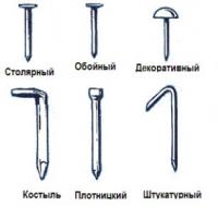 Nail Making Business How to Make Copper Nails
 Stone brazier: material features and manufacturing options
 Blackroot medicinal cultivation
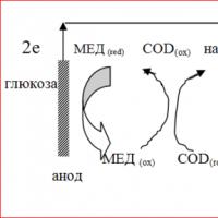 Fuel cells: a glimpse into the future
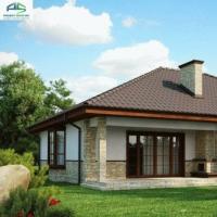 Houses with a hipped roof projects